

How to Cut and Drill FRP Pultruded Profiles: Tools, Safety and Fabrication Tips
FRP pultruded profiles are widely used in industrial structures, equipment frames, cable support systems and corrosion-resistant platforms. Common shapes include fiberglass I-beams, C-channels, angles, square tubes and rectangular tubes. Although these profiles can be fabricated to suit different project requirements, cutting and drilling them correctly is essential for achieving accurate dimensions and reliable connections.
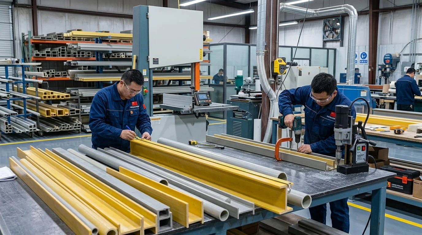
Unlike steel sections, fiberglass-reinforced plastic profiles consist of reinforcing fibers embedded in a resin matrix. Improper machining can cause fiber damage, rough edges, local delamination or unnecessary exposure to airborne dust.
This guide explains how to prepare FRP profiles for fabrication, choose appropriate tools, cut and drill components, inspect machined surfaces and maintain a safe working environment.
1. Understanding FRP Pultruded Profile Fabrication
FRP pultruded profiles are manufactured by pulling reinforcing fibers through a resin system and a forming die. The process creates continuous profiles with a consistent cross-sectional shape along their length.
Common products include FRP pultruded structural profiles, such as beams, channels, angles and hollow tubes. These products can be cut to length and, when permitted by the product specifications, drilled or otherwise machined for assembly.
Why Machining Requires Special Attention
The mechanical properties of FRP depend on the reinforcing fibers, resin system and profile construction. Cutting across the fibers exposes the composite structure, while drilling removes material and creates a localized stress concentration.
Good fabrication practice helps reduce the risk of:
- Splintering or rough edges around cut surfaces.
- Cracking or delamination near drilled holes.
- Dimensional errors that make assembly difficult.
- Damage caused by excessive tool pressure or heat.
- Unnecessary exposure to fiberglass dust and particles.
2. Tools for Cutting FRP Pultruded Profiles
The appropriate cutting tool depends on the profile dimensions, wall thickness, required cut quality, production volume and manufacturer's recommendations. Tools should be selected for composite materials rather than chosen solely because they are commonly used for metal.
Carbide-Tipped Cutting Tools
Carbide-tipped blades and suitable carbide cutting tools are commonly considered for machining fiberglass composites. The blade geometry, tooth configuration and operating speed should be compatible with the specific FRP material and equipment.
Before production cutting, confirm the tool manufacturer's guidance and carry out a controlled trial on a sample when appropriate. Inspect the resulting cut for roughness, fiber pull-out and visible damage.
Diamond- or Abrasive-Based Tools
Some fabrication operations use suitable diamond-coated or abrasive cutting tools for fiberglass-reinforced materials. Their suitability depends on the equipment, material construction and required finish.
Tool wear, heat generation and dust extraction should be considered when selecting an abrasive cutting method. A tool that produces an acceptable cut on one profile may not provide the same result on every resin system or cross-sectional thickness.
Choosing the Right Cutting Equipment
For workshop production, the cutting setup should provide stable workpiece support, accurate positioning and suitable dust collection. For on-site work, portability may also matter, but it should not compromise guarding, cutting accuracy or operator protection.
Follow the equipment manufacturer's operating instructions and the FRP supplier's fabrication guidance. Do not assume that one blade type or cutting speed is suitable for all fiberglass profiles.
3. How to Cut FRP Pultruded Profiles Step by Step
A controlled cutting process improves dimensional accuracy and helps identify defects before components are installed.
Step 1: Confirm the Drawings and Dimensions
Review the approved fabrication drawings before cutting. Confirm the profile type, cross-sectional dimensions, finished length, cut angle and any machining allowance.
For assemblies involving several members, check whether the components require square cuts, angled cuts or matched lengths. Clarify any uncertainty before material is removed.
Step 2: Measure and Mark the Profile
Use a suitable measuring tool and marking method to identify the cut line. Measure from a consistent reference point and verify the finished length before cutting.
For repeated components, a suitable jig or stop can help maintain consistency. Check that the setup does not damage the profile surface or interfere with the cutting operation.
Step 3: Secure and Support the Workpiece
Support the profile close enough to the cutting area to reduce vibration and unwanted movement. Long beams and tubes may require additional supports to prevent sagging or shifting during cutting.
Clamping pressure should be sufficient to hold the component securely without crushing or damaging the composite profile. Keep hands clear of the blade and follow the equipment's guarding requirements.
Step 4: Make the Cut Using a Controlled Feed
Use the cutting speed and feed procedure recommended for the selected tool and FRP material. Avoid forcing the blade through the workpiece, as excessive pressure may increase heat, roughness or local damage.
Maintain a stable cutting path and do not adjust or reposition the profile while the blade is moving. If abnormal vibration, overheating or visible material damage occurs, stop the operation and inspect the setup.
Step 5: Inspect and Finish the Cut Edge
After cutting, inspect the end face for dimensional accuracy, splintering, delamination and exposed or damaged fibers. Remove loose particles using a suitable method that does not spread dust into the surrounding work area.
Where required by the product specification or project design, apply a compatible resin or edge-sealing system to exposed cut surfaces. Sealing requirements depend on the product, resin system, operating environment and manufacturer's instructions; it should not be assumed that every cut requires the same treatment.
4. How to Drill FRP Pultruded Profiles
Drilling is often required when FRP profiles are assembled using bolts, brackets, connection plates or other mechanical fasteners. Hole location and quality can influence both installation accuracy and the performance of the completed joint.
Select a Suitable Drill Bit
Use a drill bit recommended for fiberglass-reinforced composites and compatible with the required hole size and finish. Suitable carbide or other composite-compatible tooling may be used depending on the material and equipment.
Check the drill bit's condition before use. A worn or unsuitable bit may increase heat, produce rough hole edges or contribute to fiber damage.
Mark Hole Positions Carefully
Locate hole centers according to the approved drawings. Confirm hole diameter, spacing, edge distance and alignment with the mating component before drilling.
These dimensions must be established by the connection design. There is no universal hole spacing or edge-distance rule that applies to every FRP profile, fastener and loading condition.
Support the Material During Drilling
Support the profile near the drilling location where practical. For hollow tubes and thin-walled sections, consider how the drilling setup may affect the opposite wall and whether the approved fabrication procedure requires additional backing or support.
Avoid excessive feed pressure. If the drilling operation produces cracking, unusual vibration or visible delamination, stop and assess the component before proceeding.
Keep Holes Clean and Inspect Their Edges
Remove drilling debris using a suitable dust-control method. Inspect each hole for cracking, splintering, rough edges or other signs of damage.
Do not enlarge or relocate a hole to compensate for poor alignment unless the change has been approved. Unplanned machining can reduce the remaining material around the hole and affect connection performance.
5. Dust Control and Personal Protective Equipment
Cutting and drilling FRP can release fine fiberglass and resin-containing dust. Appropriate controls are important for protecting workers and preventing dust from spreading through the workshop or installation area.
Use Effective Dust Extraction
Where practicable, use suitable local exhaust ventilation or dust extraction near the cutting or drilling point. Select equipment designed for the type of dust being generated, and maintain it according to the manufacturer's instructions.
Avoid dry sweeping or compressed-air cleaning methods that disperse accumulated dust into the air. Use a suitable industrial vacuum or another approved cleanup method.
Wear Appropriate Protective Equipment
Follow the product safety information, workplace risk assessment and applicable occupational safety requirements. Depending on the task, protective measures may include:
- Safety glasses or suitable eye protection.
- Protective clothing and gloves appropriate for fiberglass handling.
- Suitable respiratory protection where required by the risk assessment.
- Hearing protection when operating noisy machinery.
Respiratory protection should be selected according to the exposure assessment and local regulations. It should complement, not replace, effective engineering controls.
Maintain a Clean Work Area
Keep cutting and drilling areas organized, remove accumulated dust safely and prevent debris from contaminating adhesives or prepared bonding surfaces. Follow workplace procedures for collecting and disposing of fiberglass composite waste.
6. Fabrication Considerations for Different FRP Profile Shapes
Different cross-sections create different handling and machining challenges. The final fabrication procedure should be confirmed against the actual profile and project drawings.
FRP I-Beams and Channels
FRP I-beams and channels are often used in industrial support frames and structural assemblies. Their flanges and webs may serve different structural functions, so the cut location and drilled-hole positions must follow the approved design.
Support long sections adequately during machining, and inspect cut ends and connection areas before assembly. Avoid placing holes or making additional cuts in structural regions without engineering approval.
FRP Angles
FRP angles are commonly used for braces, brackets and secondary framing. Their two legs can make accurate positioning important, especially where several angles must meet at a common joint.
Use a stable fixture when cutting repeated pieces or drilling holes near an edge. Check that the finished geometry matches the connection drawing before installation.
FRP Square and Rectangular Tubes
Hollow FRP tubes are used in frames, supports and other lightweight structural assemblies. Their walls must be protected from crushing during clamping, drilling and fastening.
Before machining a hollow section, confirm its wall thickness, connection details and any specified internal reinforcement. Avoid applying excessive clamping force or drilling additional holes without checking the design requirements.
Explore FRP square tubes and fiberglass rectangular tubes for potential structural applications.
7. Common FRP Machining Problems and Prevention
| Problem | Possible cause | Preventive measure |
|---|---|---|
| Rough cut edges | Unsuitable tooling, excessive feed or inadequate support | Use compatible tools and a stable cutting setup |
| Cracking or delamination | Excessive pressure, unsuitable tooling or poor workpiece support | Follow the approved machining procedure and inspect the material |
| Incorrect finished length | Measurement or positioning errors | Verify dimensions and use suitable stops or jigs for repeated cuts |
| Poor hole alignment | Incorrect marking or inconsistent positioning | Check hole coordinates and mating components before drilling |
| Excessive airborne dust | Insufficient extraction or unsuitable cleanup methods | Use appropriate extraction, protective equipment and cleanup procedures |
| Damaged tube walls | Excessive clamping pressure or unsupported drilling | Use suitable fixtures and follow the profile-specific fabrication instructions |
8. Quality Inspection Before Assembly
Machined FRP components should be inspected before they are installed in a structural assembly. Early inspection helps identify problems while corrective action is still practical.
Dimensional Checks
Verify finished lengths, cut angles, hole diameters and hole locations against the approved drawings and applicable tolerances. Check that mating components align correctly without forcing them into position.
Visual Inspection
Inspect cut edges, drilled holes and nearby surfaces for visible damage. Components showing significant cracking, delamination or other defects should be set aside for assessment rather than installed without review.
Documentation and Traceability
For projects with formal quality requirements, record relevant inspection results and identify any nonconforming components. Repairs, additional machining or changes to connection details should follow an approved procedure.
9. What to Confirm Before Ordering FRP Profiles for Fabrication
Planning the fabrication requirements before ordering can help reduce material waste and avoid unnecessary machining at the installation site.
When requesting a quotation or discussing a project with a supplier, provide:
- Profile shape, dimensions and required lengths.
- Required quantities and cut-length schedule.
- Drilling locations and connection drawings, where available.
- Operating environment, including chemical exposure and temperature.
- Required surface finish and any specified edge treatment.
- Quality inspection criteria and applicable project requirements.
- Whether cutting, drilling or other fabrication services are required.
Confirm the availability of fabrication services with the supplier before assuming that profiles will be delivered with specific cuts or drilled holes. Final machining procedures should be compatible with the supplied product and approved project design.
Conclusion
Cutting and drilling FRP pultruded profiles requires appropriate tooling, accurate measurement, stable workpiece support and effective dust control. Careful machining and inspection help minimize edge damage, improve dimensional accuracy and prepare components for reliable assembly.
Whether working with fiberglass I-beams, channels, angles or hollow tubes, follow the manufacturer's fabrication recommendations and the approved engineering drawings. Pay particular attention to drilled-hole locations, exposed cut edges and any signs of composite damage before installation.
Contact Preet Grating for FRP Pultruded Profiles
Looking for FRP pultruded profiles for industrial structures, equipment frames or corrosion-resistant support systems? Contact Preet Grating with your required profile dimensions, lengths, quantities and fabrication drawings to discuss suitable product options.
WhatsApp: +86 138 5147 5666
Email: info@preet.cn
Product Range: Explore FRP Pultruded Profiles


