

FRP Pultruded Profiles Connection Methods: Bolted Joints, Adhesives and Installation Tips
FRP pultruded profiles, including fiberglass I-beams, channels, angles, square tubes and rectangular tubes, are widely used in industrial structures, equipment frames, walkways and corrosion-resistant support systems. However, selecting the right profile is only one part of structural design. The connection method also plays an important role in load transfer, dimensional stability, installation quality and long-term performance.
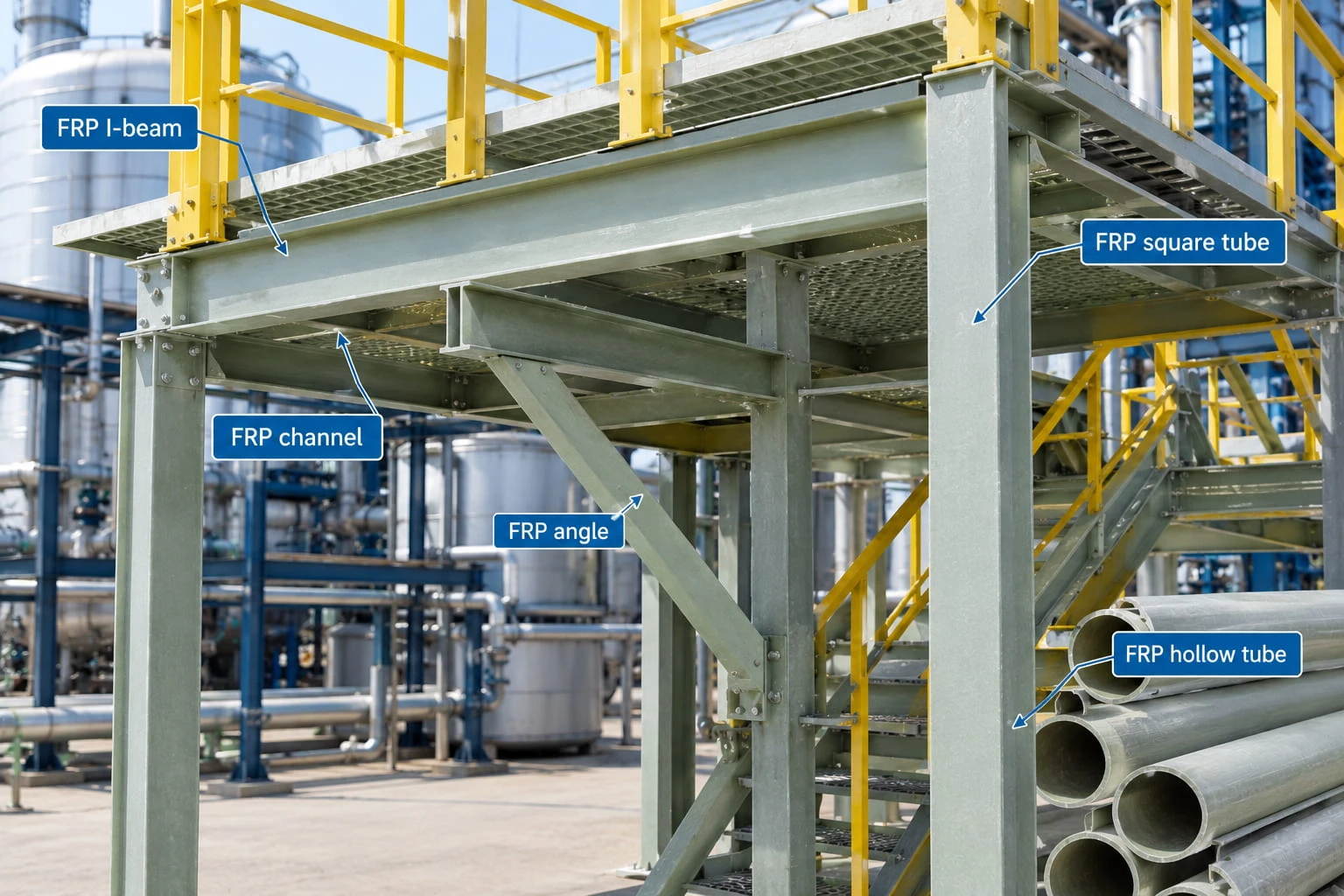
Unlike conventional steel components, fiber-reinforced polymer profiles have a composite structure consisting of reinforcing fibers and a resin matrix. Their behavior around drilled holes, concentrated loads and fasteners therefore needs to be considered during connection design.
This guide explains common FRP profile connection methods, key installation precautions and the information engineers should confirm before fabrication and assembly.
1. Why Connection Design Matters for FRP Structural Profiles
A structural profile may have sufficient strength for its intended application, but a poorly designed connection can still become a weak point. Connection design should consider the applied loads, profile geometry, fiber orientation, environmental conditions and the type of supporting structure.
Load Transfer at Connection Points
Connections transfer forces between individual profiles and other structural components. Depending on the application, a joint may experience tension, compression, shear, bending or a combination of these forces.
For example, an FRP I-beam connected to a column may require a different joint arrangement from a fiberglass angle used as a secondary brace. The connection should be designed for the actual load path rather than selected solely according to convenience.
Composite Material Behavior
FRP profiles are anisotropic composite materials, meaning their mechanical properties can vary with direction. Drilling, cutting or applying concentrated pressure in an unsuitable location can damage fibers or create local stress concentrations.
Connection details should therefore follow the manufacturer's recommendations and the engineering requirements for the specific profile, laminate structure and application.
2. Common Connection Methods for FRP Pultruded Profiles
Three approaches are commonly considered for assembling FRP structural components: mechanical fastening, adhesive bonding and engineered hybrid connections. The appropriate method depends on the required load transfer, accessibility, service environment and maintenance requirements.
Bolted Connections
Bolted connections are widely used when FRP profiles need to be assembled on site, inspected periodically or disassembled for maintenance. Bolts can connect fiberglass beams, channels, angles and hollow sections to compatible brackets, plates or other structural members.
Important design considerations include:
- Hole location: Maintain the edge distances, spacing and hole dimensions specified in the approved design.
- Local bearing: Check the material around each hole for bearing stress, splitting and other possible failure modes.
- Fastener selection: Choose bolts, nuts and washers suitable for the loads and operating environment.
- Clamping pressure: Avoid excessive tightening that could crush or damage the composite material.
- Load distribution: Use suitable plates or washers where required to distribute force across the connection area.
Stainless steel or other corrosion-resistant fasteners may be appropriate in demanding environments, but the selection must account for chemical compatibility, temperature and the materials being joined.
Adhesive-Bonded Connections
Adhesive bonding can distribute loads across a bonded surface rather than concentrating all forces at individual bolt holes. It may be considered for selected FRP assemblies where the adhesive, surface preparation and joint geometry have been properly engineered.
Successful bonding depends on several factors:
- Compatibility between the adhesive and the FRP resin surface.
- Correct surface preparation and removal of dust, oil or other contaminants.
- Suitable bond-line thickness and joint geometry.
- Controlled curing conditions in accordance with the adhesive manufacturer's instructions.
- Resistance to the chemicals, moisture and temperatures expected during service.
Adhesive joints are not automatically suitable for every structural application. Their load capacity and durability should be verified for the intended service conditions, and temporary fixtures may be needed while the adhesive cures.
Hybrid Connections
Some assemblies combine mechanical fasteners and adhesive bonding. A hybrid connection may help meet specific requirements for load transfer, alignment or vibration resistance, but its performance depends on how the two connection methods interact.
Engineers should not assume that combining bolts and adhesive automatically increases joint strength. The design should establish how loads are shared, how the joint behaves during installation and how it will be inspected throughout its service life.
3. Connection Considerations for Different FRP Profile Shapes
Profile geometry affects how connections can be arranged. The following points are general design considerations rather than universal connection specifications.
FRP I-Beams
FRP I-beams are commonly considered for beams, support frames and platform structures. Their flanges and web serve different structural functions, so the connection location and load direction matter.
Connection details should avoid unverified concentrated loads and should account for local stresses around holes or brackets. For projects involving significant bending or shear forces, the joint should be checked as part of the complete structural system.
Explore the FRP pultruded profiles range when evaluating fiberglass structural components for a project.
FRP Channels and Angles
FRP channels and angles are often used as supports, braces, framing members and secondary structural components. Their open cross-sections can simplify some assembly arrangements, but they may also introduce eccentric loading if the connection is not aligned with the applied force.
Where a channel or angle connects to a plate or another profile, engineers should evaluate the force direction, fastener arrangement, local bearing and the possibility of rotation or deformation.
Learn more about FRP C channels for industrial framing and support applications.
Hollow FRP Square and Rectangular Tubes
Hollow fiberglass tubes can be used in equipment frames, support structures and lightweight assemblies. Their hollow cross-sections require particular care when bolts pass through the walls.
Excessive tightening force may damage a tube wall, while a poorly arranged connection can create local crushing or stress concentration. Depending on the design, engineered inserts, internal reinforcement or external connection plates may be considered.
Any insert or reinforcement should be compatible with the profile and validated for the intended loads. Do not assume that a hollow tube can safely accept a bolt through its wall without checking the wall thickness and connection design.
For relevant product options, see the FRP square tube and fiberglass rectangular tube pages.
4. Drilling and Fabrication Precautions
Accurate fabrication helps reduce installation problems and the risk of damaging composite profiles. Drilling and cutting should follow the profile manufacturer's instructions and the approved fabrication drawings.
Confirm Hole Positions Before Drilling
Check the dimensions, reference edges, hole centers and required clearances before machining. If multiple components are connected, verify their alignment using the approved drawings or a suitable template.
Hole spacing and edge distances should be determined by the structural design. There is no single spacing rule that is suitable for every FRP profile, thickness, fastener size and loading condition.
Use Suitable Tools and Control Dust
Use tooling appropriate for fiberglass-reinforced composites. Support the workpiece adequately during machining, and avoid excessive force or heat that may damage the laminate.
Fiberglass machining can generate airborne dust and fine particles. Follow the manufacturer's safety guidance and workplace procedures, including appropriate eye protection, respiratory protection, dust extraction and cleanup.
Inspect Machined Areas
After drilling or cutting, inspect the edges and surrounding material for visible cracking, delamination, splintering or other damage. Damaged components should be evaluated before installation rather than concealed by fasteners or connection plates.
5. Fastener Selection and Tightening
Fasteners should be selected according to the structural design and service environment. In addition to bolt strength, the connection must account for the FRP material's local bearing capacity and its response to clamping pressure.
Choose Materials for the Operating Environment
Industrial structures may be exposed to moisture, salt spray, cleaning agents, acids, alkalis or other chemicals. Fasteners, washers, brackets and any inserts should be checked for compatibility with both the FRP components and the surrounding environment.
When dissimilar materials are used in the same assembly, consider corrosion risks and any isolation requirements specified by the design.
Avoid Over-Tightening
Metal connections can often tolerate tightening practices that are unsuitable for composite components. Excessive torque may crush the FRP around a hole, damage the surface or create internal damage that is not immediately visible.
Use the specified tightening procedure and torque requirements when provided by the engineered connection design. Do not apply a generic metal-joint torque value to an FRP connection without verification.
6. Installation Checklist for FRP Profile Assemblies
Before an FRP structural assembly is put into service, the installation team should verify that the components and connections match the approved design.
- Confirm the profile type, dimensions and material specifications.
- Check that components are free from visible transport or fabrication damage.
- Verify connection locations, hole positions and alignment.
- Confirm that fasteners, washers, brackets and inserts match the design.
- Inspect bonded joints for compliance with the specified preparation and curing procedure.
- Check that fasteners are tightened according to the approved requirements.
- Confirm that the assembly is adequately supported and that its load path matches the design.
- Record any deviations and obtain engineering approval before accepting changes.
For critical structures, connection inspection and acceptance criteria should be defined before installation begins. Any repair or modification should follow a documented procedure approved by the responsible engineer.
7. Common FRP Connection Problems and How to Prevent Them
| Potential problem | Possible cause | Prevention |
|---|---|---|
| Cracking around holes | Unsuitable hole position, excessive clamping or local overload | Follow engineered hole details and tightening requirements |
| Tube wall crushing | Excessive bolt pressure or inadequate local support | Use an approved connection design and validated reinforcement where required |
| Joint misalignment | Incorrect measurements or uncontrolled fabrication tolerances | Verify drawings, hole locations and component fit before final assembly |
| Adhesive joint failure | Incompatible adhesive, poor preparation or incorrect curing | Follow the adhesive manufacturer's procedure and validate the joint design |
| Fastener corrosion | Unsuitable fastener material for the environment | Check chemical exposure and specify compatible corrosion-resistant materials |
8. What to Confirm Before Ordering FRP Structural Profiles
Providing connection requirements early helps suppliers assess whether the proposed profile and fabrication arrangement are appropriate for the project.
When requesting a quotation, consider supplying the following information:
- Profile type, cross-sectional dimensions and required lengths.
- Required quantities and any cutting or drilling requirements.
- Connection drawings, including hole positions and bracket details where available.
- Expected loads, support conditions and intended structural function.
- Operating environment, including chemical exposure, moisture and temperature.
- Required resin, surface finish, color or other material requirements.
- Applicable project standards and inspection requirements.
Final structural dimensions, connection capacities and fabrication details should be verified by the responsible engineer using the actual product data and project conditions.
Conclusion
Reliable FRP pultruded profile assemblies depend on more than choosing the right I-beam, channel, angle or hollow tube. Bolted joints, adhesive bonding and hybrid connections each have different design and installation requirements. Careful attention to load transfer, hole placement, fastener compatibility, tightening and inspection helps reduce avoidable connection problems.
For industrial projects using fiberglass structural profiles, coordinate the profile specifications and connection details early in the design process. This helps ensure that the selected components are suitable for the intended assembly and operating environment.
Contact Preet Grating for FRP Profile Requirements
Looking for FRP pultruded profiles for industrial structures, equipment frames or corrosion-resistant support systems? Share your profile dimensions, required quantities, application environment and available drawings with our team to discuss suitable product options.
WhatsApp: Contact us on WhatsApp
Email: info@preet.cn
Product range: Explore FRP Pultruded Profiles


