

Introduction
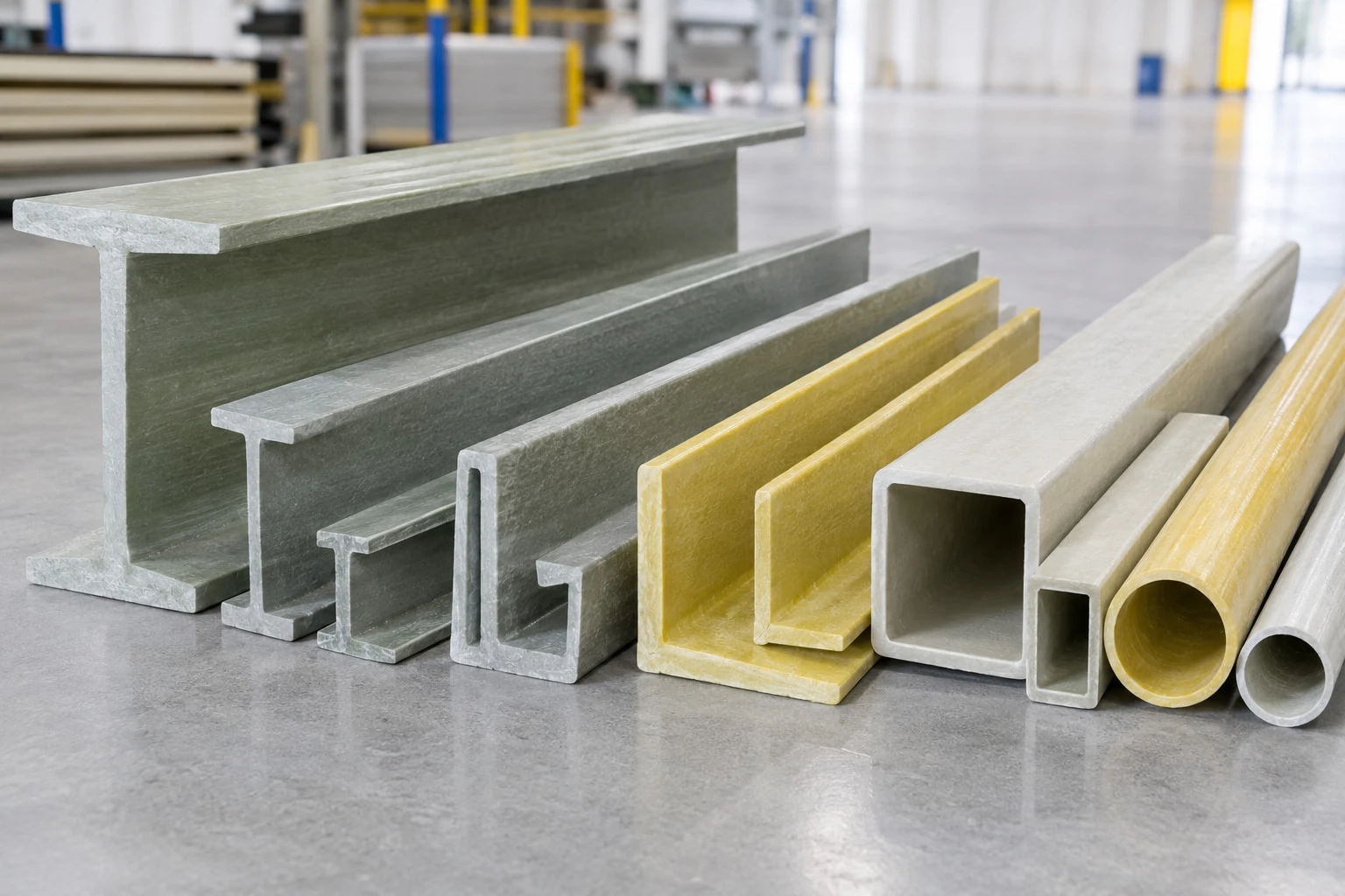
Fiberglass reinforced plastic (FRP) structural profiles are used in industrial frames, equipment supports, access platforms, handrails, cable management systems, and other structures where corrosion resistance and lightweight construction are important. Available profiles include I-beams, channels, angles, square tubes, rectangular tubes, and round tubes.
Although these profiles may be manufactured from similar composite materials, their cross-sectional shapes affect how they carry loads, resist bending, connect to other components, and fit into an assembly. Selecting a profile based only on its outside dimensions or appearance can result in an inefficient or unsuitable design.
This guide compares common FRP structural profiles and explains how engineers, contractors, and purchasing teams can narrow down their options based on structural function, loading conditions, connection details, and operating environment.
1. What Are FRP Structural Profiles?
FRP structural profiles are load-bearing or supporting components made from fiber-reinforced polymer composites. In many industrial applications, they are manufactured through pultrusion, a continuous process in which reinforcing fibers are combined with resin and pulled through a heated forming die.
Pultrusion is suitable for profiles with a consistent cross-section along their length. The resulting components can be used individually or assembled into frames, platforms, supports, and other structural systems.
Common Types of FRP Profiles
- I-beams: Profiles with two flanges connected by a web, often considered for beam-like structural members.
- C-channels and U-channels: Open sections commonly used for brackets, frames, supports, and edge members.
- Angle profiles: L-shaped sections used in framing, bracing, corner connections, and secondary supports.
- Square tubes: Hollow sections with four sides, often used in frames, posts, and support assemblies.
- Rectangular tubes: Hollow sections with unequal width and height, suitable for applications where directional geometry matters.
- Round tubes: Circular hollow sections used in selected supports, tubular frames, and handrail systems.
These descriptions identify common uses rather than fixed design limits. The suitability of any profile depends on its actual dimensions, material properties, loading, span, and connection arrangement.
2. FRP I-Beams: For Beam-Like Structural Members
FRP I-beams have two flanges connected by a central web. This shape distributes material away from the central axis and can be efficient for resisting bending in the intended direction.
Depending on the product design and engineering calculations, I-beams may be considered for primary or secondary supports in industrial structures. Their use should be based on verified section properties and the applicable design requirements.
Typical Applications
- Structural frames and support beams
- Equipment support structures
- Selected platform and walkway support members
- Industrial structures exposed to corrosive environments
What to Check Before Selecting an FRP I-Beam
Review the span, loading direction, support conditions, deflection limits, and connection details. The flange and web dimensions influence the section's structural behavior, so two I-beams with similar overall heights may not have equivalent performance.
For a beam application, the engineer should verify bending, shear, deflection, stability, and connection capacity as appropriate. FRP material properties differ from those of steel, so steel beam tables and design assumptions should not be applied directly without confirming their applicability.
3. FRP Channels: For Supports, Frames and Brackets
FRP channels have an open cross-section formed by a web and two flanges. Depending on the profile geometry, they can be useful for supporting components, framing equipment, and constructing assemblies that require accessible connection surfaces.
C-channels and U-channels are related open-section profiles, but their dimensions and flange geometry may differ. Buyers should use the manufacturer's drawings to confirm the exact shape rather than assuming the two terms always refer to identical products.
Typical Applications
- Equipment and instrument supports
- Industrial frames and mounting brackets
- Handrail and ladder support assemblies
- Cable management and support structures
- Secondary framing and edge members
Selection Considerations for FRP Channels
Check the channel height, flange width, wall thickness, and section properties. Because a channel is an open section, the direction of loading and the way the member is restrained can significantly affect its behavior.
Pay particular attention to connection design. Bolts, holes, brackets, and local bearing forces can affect the performance of composite profiles. Use the manufacturer's recommended connection details and have the assembly checked where structural capacity is critical.
For available profile information, see the FRP C Channel product page.
4. FRP Angle Profiles: For Bracing and Corner Connections
FRP angle profiles have an L-shaped cross-section. Their two legs provide surfaces for fastening to adjacent components, making them useful in frames, braces, corner joints, and other secondary structural arrangements.
Angles are often selected where a compact profile or a right-angle connection is needed. However, their open, asymmetric geometry means that load direction and connection layout must be considered carefully.
Typical Applications
- Corner connections and framing
- Bracing and secondary supports
- Mounting rails and equipment supports
- Light structural assemblies
- Connections between compatible FRP components
What to Check When Choosing an FRP Angle
Confirm the length of each leg, wall thickness, available fastening area, and the direction of the applied load. For structural use, check how the angle is restrained and whether the connection introduces eccentric loading.
An angle that fits the assembly geometrically may not have sufficient capacity for the intended load. Verify its section properties and connection performance before finalizing the design.
5. FRP Hollow Tubes: Square, Rectangular and Round Profiles
Hollow FRP tubes provide enclosed cross-sections that can be useful for frames, posts, braces, and other structural members. Their suitability depends on the tube dimensions, wall thickness, material properties, and how the member is supported and connected.
FRP Square Tubes
Square tubes have four equal outer sides. Their flat faces can simplify some framing and fastening arrangements, making them candidates for posts, equipment frames, support structures, and handrail assemblies.
Selection should consider the outside dimensions, wall thickness, unsupported length, loading direction, and connection details. A larger outside dimension does not automatically guarantee greater capacity if the wall thickness and other section properties differ.
See the FRP Square Tube product page for product information.
FRP Rectangular Tubes
Rectangular tubes have different width and height dimensions. This geometry can be useful where the available installation space or structural demands differ between two directions.
Because the section is not symmetrical in the same way as a square tube, its orientation can influence stiffness and bending behavior. The designer should verify the loading direction and the manufacturer's section data before selecting the profile.
View the Fiberglass Rectangular Tube product page for additional information.
FRP Round Tubes
Round tubes have a circular hollow cross-section and may be used in tubular frames, handrails, selected braces, and other assemblies where a circular profile is appropriate.
Check the outside diameter, wall thickness, span, loading conditions, and joining method. Clamps, inserts, brackets, and bolted connections should be compatible with the tube's geometry and the expected loads.
See the Fiberglass Round Tube product page for available product information.
6. FRP Profile Comparison: Which Shape Should You Choose?
The following table provides a preliminary comparison of common FRP profile types. It is intended to help identify which geometries may be worth evaluating, not to replace structural calculations.
| Profile Type | Cross-Section | Potential Uses | Main Checks |
|---|---|---|---|
| I-beam | Two flanges joined by a web | Beam-like supports and structural frames | Bending, shear, deflection, stability, connections |
| C-channel or U-channel | Open channel section | Brackets, frames, equipment and cable supports | Load direction, torsional behavior, flange and connection capacity |
| Angle | L-shaped section | Bracing, corner joints and secondary framing | Eccentricity, local forces, fastening area |
| Square tube | Square hollow section | Posts, frames, handrails and supports | Wall thickness, span, local loading and joints |
| Rectangular tube | Rectangular hollow section | Frames and members with directional space constraints | Orientation, stiffness in each direction, connections |
| Round tube | Circular hollow section | Tubular frames, handrails and selected braces | Diameter, wall thickness, support, joining method |
When two profile types appear suitable, compare their verified section properties and the performance of the complete assembly. Profile shape alone does not establish a safe working load.
7. Key Factors for Selecting FRP Structural Profiles
After identifying a suitable cross-section, review the engineering and environmental requirements before deciding on the final product.
Loading and Span
Establish the expected loads, unsupported span, support arrangement, and applicable deflection limits. Depending on the application, the assessment may include bending, shear, axial force, torsion, stability, and local connection effects.
Use manufacturer data for the exact profile and material system. Avoid selecting dimensions based solely on a visual comparison with steel profiles or another FRP section.
Material and Resin System
FRP properties depend on the fiber reinforcement, resin formulation, manufacturing process, and profile geometry. Chemical exposure, temperature, moisture, and ultraviolet radiation should be considered when determining whether a product is suitable for the operating environment.
For corrosive applications, provide the supplier with details about the chemicals involved, concentrations, temperature, and exposure duration. Obtain product-specific compatibility information rather than assuming all FRP profiles have identical resistance.
Connection Design
Connection design is a critical part of FRP structural assemblies. Review bolt-hole positions, edge distances, washers, brackets, inserts, and any required local reinforcement. The connection should transfer the intended loads without introducing unacceptable local stresses or damage.
Confirm that the proposed fasteners and adjacent materials are compatible with the site environment. Corrosion resistance of the FRP profile does not automatically guarantee the same performance for metal fasteners.
Installation and Fabrication
Check available lengths, cutting requirements, drilling permissions, transport limitations, and installation access. Field modifications should follow the manufacturer's instructions and the approved design, especially when a profile is part of a load-bearing assembly.
Plan how the profiles will be aligned, supported, and connected before ordering. Early coordination can reduce unnecessary cutting and help prevent interference with adjacent equipment.
Cost and Lifecycle Considerations
Purchase price is only one part of the selection decision. Depending on the application, the comparison may also include transportation, installation labor, corrosion protection, inspection, maintenance, and replacement requirements.
Evaluate alternatives using the same project assumptions. A profile with a lower unit price may not be the most economical choice if it requires additional supports, more complex connections, or greater maintenance.
8. Common Mistakes When Choosing FRP Profiles
Selecting by Dimensions Alone
Two profiles with similar outside dimensions may have different wall thicknesses, cross-sectional areas, and structural properties. Compare the exact profile drawings and verified technical data before making a decision.
Assuming FRP Behaves Like Steel
FRP is an anisotropic composite material whose properties can differ by direction. Its stiffness, failure behavior, and connection performance are not identical to those of conventional steel. Structural calculations should use appropriate composite design data and methods.
Ignoring Connection Capacity
A profile may have adequate capacity along its length while the connection remains the critical part of the assembly. Evaluate fasteners, bearing areas, edge distances, brackets, and load transfer as part of the complete design.
Overlooking the Operating Environment
Different resin systems and product constructions can respond differently to chemicals, temperature, moisture, and outdoor exposure. Confirm suitability for the actual service conditions before ordering.
Using Unverified Load Values
Do not assume that a generic load value applies to every profile of a given size. Capacity depends on the exact product, span, support conditions, loading direction, connection details, and applicable design criteria.
9. What Information Should You Provide to an FRP Profile Supplier?
Providing clear project information helps a supplier identify suitable profiles and prepare a more useful quotation.
- Application: Explain whether the profile will be used for a beam, frame, brace, handrail, equipment support, or another purpose.
- Dimensions: Provide the required cross-section, wall thickness, length, and dimensional tolerances where applicable.
- Design conditions: Share the expected loading, span, support arrangement, and relevant engineering requirements.
- Environment: Identify chemical exposure, moisture, outdoor conditions, temperature, and other relevant site factors.
- Connection details: Provide drawings or describe how the profile will attach to adjacent components.
- Quantity and processing: Specify the required quantity, lengths, cutting requirements, and any project-specific customization.
- Documentation: Identify the standards, test reports, drawings, and quality documents required for project approval.
Where the profile is part of a load-bearing structure, final selection and connection design should be reviewed by a qualified engineer using verified product data.
Conclusion
FRP I-beams, channels, angles, and hollow tubes each offer different geometric characteristics for industrial structures. I-beams may be considered for beam-like members, channels for selected supports and frames, angles for bracing and corner connections, and hollow tubes for posts and tubular assemblies.
The correct choice depends on the structural function, loading conditions, span, material properties, connection design, and operating environment. No single profile shape is automatically the best option for every application.
Start by defining the required structural function, then compare the exact profile dimensions and verified section properties. Confirm environmental compatibility and connection details before finalizing the design or placing an order.
Contact PREET Grating
Looking for FRP pultruded profiles for an industrial structure, support frame, handrail, or equipment assembly? Share your required profile shape, dimensions, quantity, operating environment, and project drawings with our team to discuss available products and customization options.
Explore: FRP Pultrusion Profiles
WhatsApp: Contact us on WhatsApp
Email: info@preet.cn


